Leave your message

-
Leon Zhang sales consultant
-
Email: zxl635973785@gmail.com
-
Phone/WhatsApp/Wechat: +86 13655813266

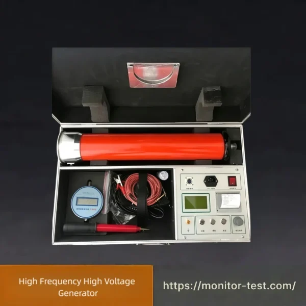
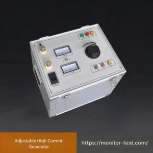
HF-HG-305 High Frequency High Voltage Generator
High Frequency High Voltage Generator provides adjustable high-frequency high voltage output. It is commonly used for partial discharge detection, electrostatic experiments and insulation performance evaluation of electrical components.
Send your requirements, we will quote for you within 12 hours
The HF-HG-305 series adopts computer control technology to realize PWM pulse modulation, measurement, protection and display. The LCD screen displays DC high voltage, current, overvoltage setting, timing and protection information, and is equipped with RS232 interface for computer communication.
The intelligent DC high voltage generator adopts sectional structure, applicable for both high and low voltage levels with constant precision. Take the 100/200kV/2mA two-section model as an example: single section can operate at 100kV/4mA for DC withstand tests of 35kV and below electrical equipment, avoiding mismatched range selection. Two sections connected in series can reach 200kV/2mA, suitable for DC tests of 220kV voltage dividers, 110kV and below ZnO arresters as well as DC withstand voltage tests of cross-linked cables. It achieves true dual-mode operation and greatly facilitates on-site testing.
The intelligent DC high voltage generator adopts sectional structure, applicable for both high and low voltage levels with constant precision. Take the 100/200kV/2mA two-section model as an example: single section can operate at 100kV/4mA for DC withstand tests of 35kV and below electrical equipment, avoiding mismatched range selection. Two sections connected in series can reach 200kV/2mA, suitable for DC tests of 220kV voltage dividers, 110kV and below ZnO arresters as well as DC withstand voltage tests of cross-linked cables. It achieves true dual-mode operation and greatly facilitates on-site testing.
Main Features
- Adopts computer control technology to realize PWM pulse modulation, measurement, protection and display. The LCD displays output DC high voltage, current, overvoltage setting, timing and protection status, with RS232 communication interface.
- Sectional design supports both high and low voltage test levels without precision degradation. Single-section and series connection modes satisfy different test requirements, realizing one unit for multiple applications.
- Equipped with grounding fault alarm and interlock protection (voltage boost disabled with poor grounding), voltage measuring circuit break protection and emergency stop button, significantly improving operator safety during testing.
- Built on 30–50kHz high-frequency voltage boosting circuit, PWM modulation and high-power IGBT devices. Special shielding, isolation and grounding measures based on EMC theory guarantee high performance; the unit can withstand rated voltage discharge without damage.
- Adopts voltage negative feedback to greatly enhance voltage stability. A dedicated 0.75 UDC–1mA trigger button is designed for ZnO arrester tests. Operating frequency raised to 30–50kHz reduces the size and weight of control unit and voltage multiplier stack for easier field transportation.
- Selects high-quality components from the US, Japan and internationally standardized series modules manufactured in Germany, integrating practicality and elegant appearance.
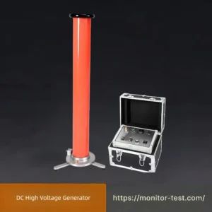
- The voltage multiplier cylinder adopts specially optimized German technology. Compact size and large capacity. Hidden tripod supports inside the base: deployed horizontally during operation and folded inside the base for transport.
- Multiple protection functions: low-voltage overcurrent, low-voltage overvoltage, high-voltage overcurrent, high-voltage overvoltage, zero-position protection, grounding protection. Sensors and isolation components feature nanosecond response speed, cutting off main circuit within about 10 microseconds. Fast drive protection with nanosecond optocouplers and analog switches can interrupt driving signals within 2 microseconds even under output short-circuit to protect power devices.
- The fully shielded auto-ranging high voltage microammeter has a metal housing. Conductive glass connects the LCD panel with the enclosure; no external buttons. Test wires are routed coaxially to achieve complete shielding. The 4½-digit ammeter auto-ranges from 0–2000μA and improves resolution of leakage current measurement.
Technical Parameters
- Power Supply: AC220V (-20% ~ +10%), 50Hz
- Working Mode: Intermittent operation, rated load duration 60 minutes
- Voltage Measurement Accuracy: 1.0% (full scale) ±2 digits
Current Measurement Accuracy
- Low-voltage side auto-ranging; total current accuracy: 1.0% (full scale) ±2 digits
- High-voltage side adopts fully shielded auto-ranging high-precision microammeter, 4½-digit display. Conductive glass is connected to metal housing for shielding. Measuring range: 0–2000μA, accuracy 1.0% ±2 digits
- Optional external infrared transmission microammeter and handheld receiver. Read leakage current at high voltage terminal remotely when direct observation is inconvenient.
The unit is controlled by computer with PWM modulation, measurement, protection and display. Large LCD screen shows output voltage, leakage current, overvoltage setting value, timer and Chinese alarm prompts with backlight. Adjustable timer with audible alarm upon timeout.
- Operating Frequency: 40kHz, closed-loop negative feedback
- Ripple Coefficient: ≤0.5%
- 0.75 Function: Press the 0.75UDC button during arrester tests; voltage automatically locks at 75%, accuracy ≤1.0%
Grounding Requirement: The test circuit must be reliably grounded; otherwise the unit refuses to boost and triggers audible alarm.
If powered via isolation transformer or portable generator, one power line terminal must be grounded. When reliable grounding is unavailable on site, hold the 75%UDC/1mA button for 2–3 seconds to clear the alarm and resume testing.
If powered via isolation transformer or portable generator, one power line terminal must be grounded. When reliable grounding is unavailable on site, hold the 75%UDC/1mA button for 2–3 seconds to clear the alarm and resume testing.
- Overvoltage Setting Error: ≤1.0%, software setting
- Voltage Adjustment Resolution: 0.1%
- Voltage Regulation Performance: Output voltage fluctuation ≤1.0% when mains voltage varies within 220V±10%
Safety Performance
- Overcurrent Protection: Upon high-voltage short circuit, output cuts off instantly without equipment damage. Equipped with Chinese text and audible alarm.
- Overvoltage Protection: Automatically shuts down output when voltage exceeds preset threshold to prevent test sample breakdown damage. Menu-based setting with Chinese text and audible alarm.
- Zero-position Protection: Voltage boost disabled when regulator fails to return zero, preventing hazardous residual high voltage. Supported by Chinese text and audible alarm.
- Grounding Protection: Boost prohibited and alarm activated without proper grounding to avoid personal injury. Under special field conditions without reliable ground, long press the 75% function button to temporarily disable interlock for testing.
- Internal Voltage Measuring Circuit Break Protection: Triggers alarm and prohibits voltage boost if voltage divider circuit or measuring cable is open-circuited or poorly contacted, preventing dangerous invisible high voltage and electric shock hazards. Supported by Chinese text and audible alarm.
FAQ — High Frequency High Voltage Generator
Q1: What is the High Frequency DC High Voltage Generator used for?
A: It performs DC withstand voltage tests and leakage current measurement for ZnO lightning arresters, power cables, voltage dividers and other high-voltage electrical equipment in laboratories and on-site commissioning.
Q2: What is the advantage of sectional voltage multiplier structure?
A: Single-section or series connection is optional. One unit can realize two voltage grades, avoiding mismatched measuring range and saving procurement cost.
Q3: Why adopt high-frequency working mode instead of power frequency?
A: Operating at 30–50 kHz with IGBT and PWM technology. It greatly reduces the volume and weight of the whole set, featuring low ripple and stable output, suitable for mobile field tests.
Q4: What is the ripple coefficient of output DC voltage?
A: The ripple coefficient ≤0.5% under closed-loop negative feedback control.
Q5: What is the accuracy of voltage and current measurement?
A: Voltage measurement accuracy: 1.0%FS ±2 digits. The built-in fully shielded microammeter covers 0–2000μA with auto-ranging, effectively improving leakage current resolution.
Q6: What is the 0.75UDC function for?
A: Specially designed for lightning arrester testing. Press the button, and the output voltage will automatically stabilize at 75% rated voltage, with accuracy ≤1.0%.
Q7: Does it support data communication with computers?
A: Yes. Equipped with RS232 interface to realize data upload, remote monitoring and automatic test recording.
Q8: Can I read high-side leakage current remotely?
A: Optional infrared handheld receiver is available to read microammeter data without approaching the high voltage terminal.
Q9: What protection functions are integrated?
A: Overcurrent protection, overvoltage protection, zero-position protection, grounding protection, internal voltage measuring circuit break protection. All protections come with screen prompt and audible alarm.
Q10: Why cannot the instrument boost voltage without good grounding?
A: Ground interlock is mandatory to prevent electric shock risks. If no reliable ground is available temporarily, long press the 75%UDC button to release the alarm for emergency testing.
Reviews
There are no reviews yet.